- Overview
- Definitions
- Requirements
- Dependencies
- Design Highlights
- Functional Specification
- Logical Specification
- Conformance
- Unit Tests
- System Tests
- Analysis
- References
- Implementation Plan
Overview
All specifications must start with an Overview section that briefly describes the document and provides any additional instructions or hints on how to best read the specification.
This document is intended to be a style guide for a detail level design specification, and is designed to be viewed both through a text editor and in a browser after Doxygen processing.
You can use this document as a template by deleting all content, while retaining the sections referenced above and the overall Doxygen structure of a page with one or more component modules. You must change the Doxygen reference tags used in @page, @section, @subsection and @defgroup examples when copying this template, and adjust @ref and @subpage references in the table of contents of your own document accordingly.
Please provide a table of contents for the major sections, as shown above. Please use horizontal ruling exactly as shown in this template, and do not introduce additional lines.
It is recommended that you retain the italicized instructions that follow the formally recognized section headers until at least the DLD review phase. You may leave the instructions in the final document if you wish.
It is imperative that the document be neat when viewed textually through an editor and when browsing the Doxygen output - it is intended to be relevant for the entire code life-cycle. Please check your grammar and punctuation, and run the document through a spelling checker. It is also recommended that you run the source document through a paragraph formatting tool to produce neater text, though be careful while doing so as text formatters do not understand Doxygen syntax and significant line breaks.
Please link your DLD to the index of all detailed designs maintained in Detailed Designs.
Purpose of a DLD
The purpose of the Detailed Level Design (DLD) specification of a component is to:
- Refine higher level designs
- To be verified by inspectors and architects
- To guide the coding phase
Location and layout of the DLD Specification
The Motr project requires Detailed Level Designs in the source code itself. This greatly aids in keeping the design documentation up to date through the lifetime of the implementation code.
The main DLD specification shall primarily be located in a C file in the component being designed. The main DLD specification can be quite large and is probably not of interest to a consumer of the component.
It is required that the Functional Specification and the Detailed Functional Specification be located in the primary header file - this is the header file with the declaration of the external interfaces that consumers of the component's API would include. In case of stand alone components, an appropriate alternative header file should be chosen.
Structure of the DLD
The DLD specification is required to be sectioned in the specific manner illustrated by the dld-sample.c and dld-sample.h files. This is similar in structure and purpose to the sectioning found in a High Level Design.
Not all sections may be applicable to every design, but sections declared to be mandatory may not be omitted. If a mandatory section does not apply, it should clearly be marked as non-applicable, along with an explanation. Additional sections or sub-sectioning may be added as required.
It is probably desirable to split the Detailed Functional Specifications into separate header files for each sub-module of the component. This example illustrates a component with a single module.
Formatting language
Doxygen is the formatting tool of choice. The Doxygen @page format is used to define a separate top-level browsable element that contains the body of the DLD. The @section, @subsection and @subsubsection formatting commands are used to provide internal structure. The page title will be visible in the Related Pages tab in the main browser window, as well as displayed as a top-level element in the explorer side-bar.
The Functional Specification is to be located in the primary header file of the component in a Doxygen @page that is referenced as a @subpage from the table of contents of the main DLD specification. This sub-page shows up as leaf element of the DLD in the explorer side-bar.
Detailed functional specifications follow the Functional Specification, using Doxygen @defgroup commands for each component module.
Within the text, Doxygen commands such as @a, @b, @c and @n are preferred over equivalent HTML markup; this enhances the readability of the DLD in a text editor. However, visual enhancement of multiple consecutive words does require HTML markup.
Definitions
Mandatory. The DLD shall provide definitions of the terms and concepts introduced by the design, as well as the relevant terms used by the specification but described elsewhere. References to the M0 Glossary and the component's HLD are permitted and encouraged. Agreed upon terminology should be incorporated in the glossary.
Previously defined terms:
- Logical Specification This explains how the component works.
- Functional Specification This is explains how to use the component.
New terms:
- Detailed Functional Specification This provides documentation of ll the data structures and interfaces (internal and external).
- State model This explains the life cycle of component data structures.
- Concurrency and threading model This explains how the the component works in a multi-threaded environment.
Requirements
Mandatory. The DLD shall state the requirements that it attempts to meet.
They should be expressed in a list, thusly:
- R.DLD.Structured The DLD shall be decomposed into a standard set of section. Sub-sections may be used to further decompose the material of a section into logically disjoint units.
- R.DLD.What The DLD shall describe the externally visible data structures and interfaces of the component through a functional specification section.
- R.DLD.How The DLD shall explain its inner algorithms through a logical specification section.
- R.DLD.Maintainable The DLD shall be easily maintainable during the lifetime of the code.
Dependencies
Mandatory. Identify other components on which this specification depends.
The DLD specification style guide depends on the HLD and AR specifications as they identify requirements, use cases, &c.
Design Highlights
Mandatory. This section briefly summarizes the key design decisions that are important for understanding the functional and logical specifications, and enumerates topics that need special attention.
- The DLD specification requires formal sectioning to address specific aspects of the design.
- The DLD is with the code, and the specification is designed to be viewed either as text or through Doxygen.
- This document can be used as a template.
Logical Specification
Mandatory. This section describes the internal design of the component, explaining how the functional specification is met. Sub-components and diagrams of their interaction should go into this section. The section has mandatory subsections created using the Doxygen @subsection command. The designer should feel free to use additional sub-sectioning if needed, though if there is significant additional sub-sectioning, provide a table of contents here.
Component Overview
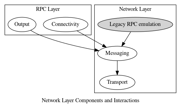
Mandatory. This section describes the internal logical decomposition. A diagram of the interaction between internal components and between external consumers and the internal components is useful.
Doxygen is limited in its internal support for diagrams. It has built in support for dot and mscgen, and examples of both are provided in this template. Please remember that every diagram must be accompanied by an explanation.
The following @dot diagram shows the internal components of the Network layer, and also illustrates its primary consumer, the RPC layer.
The @msc command is used to invoke mscgen, which creates sequence diagrams. For example:
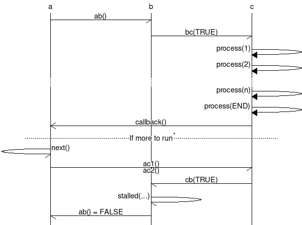
Note that when entering commands for mscgen, do not include the msc { ... } block delimiters. You need the mscgen program installed on your system - it is part of the Scientific Linux based DevVM.
UML and sequence diagrams often illustrate points better than any written explanation. However, you have to resort to an external tool to generate the diagram, save the image in a file, and load it into your DLD.
An image is relatively easy to load provided you remember that the Doxygen output is viewed from the doc/html directory, so all paths should be relative to that frame of reference. For example:

I found that a PNG format image from Visio shows up with the correct image size while a GIF image was wrongly sized. Your experience may be different, so please ensure that you validate the Doxygen output for correct image rendering.
If an external tool, such as Visio or dia, is used to create an image, the source of that image (e.g. the Visio .vsd or the .dia file) should be checked into the source tree so that future maintainers can modify the figure. This applies to all non-embedded image source files, not just Visio or dia.
Subcomponent design
Such sections briefly describes the purpose and design of each sub-component. Feel free to add multiple such sections, and any additional sub-sectioning within.
Sample non-standard sub-section to illustrate that it is possible to document the design of a sub-component. This contrived example demonstrates @subsubsections for the sub-component's data structures and subroutines.
Subcomponent Data Structures
This section briefly describes the internal data structures that are significant to the design of the sub-component. These should not be a part of the Functional Specification.
Describe briefly the internal data structures that are significant to the design. These should not be described in the Functional Specification as they are not part of the external interface. It is not necessary to describe all the internal data structures here. They should, however, be documented in Detailed Functional Specifications, though separate from the external interfaces. See Motr Sample Module Internals for example.
Subcomponent Subroutines
This section briefly describes the interfaces of the sub-component that are of significance to the design.
Describe briefly the internal subroutines that are significant to the design. These should not be described in the Functional Specification as they are not part of the external interface. It is not necessary to describe all the internal subroutines here. They should, however, be documented in Detailed Functional Specifications, though separate from the external interfaces. See Motr Sample Module Internals for example.
State Specification
Mandatory. This section describes any formal state models used by the component, whether externally exposed or purely internal.
Diagrams are almost essential here. The @dot tool is the easiest way to create state diagrams, and is very readable in text form too. Here, for example, is a @dot version of a figure from the "rpc/session.h" file:
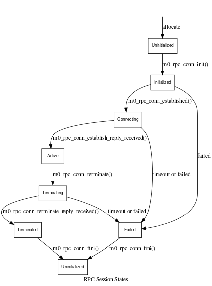
The dot program is part of the Scientific Linux DevVM.
Threading and Concurrency Model
Mandatory. This section describes the threading and concurrency model. It describes the various asynchronous threads of operation, identifies the critical sections and synchronization primitives used (such as semaphores, locks, mutexes and condition variables).
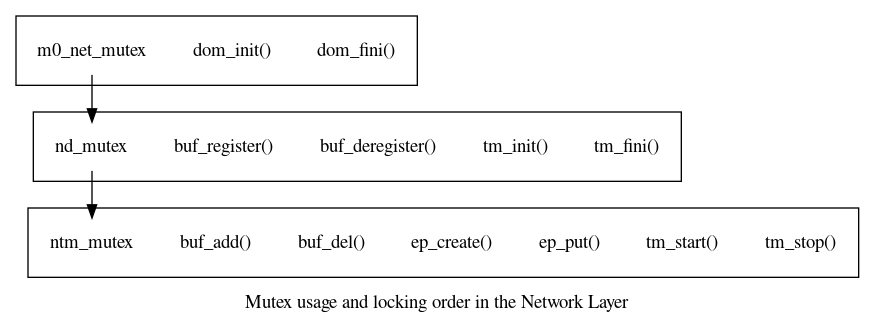
This section must explain all aspects of synchronization, including locking order protocols, existential protection of objects by their state, etc. A diagram illustrating lock scope would be very useful here. For example, here is a @dot illustration of the scope and locking order of the mutexes in the Networking Layer:
NUMA optimizations
Mandatory for components with programmatic interfaces. This section describes if optimal behavior can be supported by associating the utilizing thread to a single processor.
Conversely, it can describe if sub-optimal behavior arises due to contention for shared component resources by multiple processors.
The section is marked mandatory because it forces the designer to consider these aspects of concurrency.
Conformance
Mandatory. This section cites each requirement in the Requirements section, and explains briefly how the DLD meets the requirement.
Note the subtle difference in that I tags are used instead of the R tags of the requirements section. The I of course, stands for "implements":
- I.DLD.Structured The DLD specification provides a structural breakdown along the lines of the HLD specification. This makes it easy to understand and analyze the various facets of the design.
- I.DLD.What The DLD style guide requires that a DLD contain a Functional Specification section.
- I.DLD.How The DLD style guide requires that a DLD contain a Logical Specification section.
- I.DLD.Maintainable The DLD style guide requires that the DLD be written in the main header file of the component. It can be maintained along with the code, without requiring one to resort to other documents and tools. The only exception to this would be for images referenced by the DLD specification, as Doxygen does not provide sufficient support for this purpose.
This section is meant as a cross check for the DLD writer to ensure that all requirements have been addressed. It is recommended that you fill it in as part of the DLD review.
Unit Tests
Mandatory. This section describes the unit tests that will be designed.
Unit tests should be planned for all interfaces exposed by the component. Testing should not just include correctness tests, but should also test failure situations. This includes testing of expected return error codes when presented with invalid input or when encountering unexpected data or state. Note that assertions are not testable - the unit test program terminates!
Another area of focus is boundary value tests, where variable values are equal to but do not exceed their maximum or minimum possible values.
As a further refinement and a plug for Test Driven Development, it would be nice if the designer can plan the order of development of the interfaces and their corresponding unit tests. Code inspection could overlap development in such a model.
Testing should relate to specific use cases described in the HLD if possible.
It is acceptable that this section be located in a separate @subpage like along the lines of the Functional Specification. This can be deferred to the UT phase where additional details on the unit tests are available.
Use the Doxygen @test tag to identify each test. Doxygen collects these and displays them on a "Test List" page.
System Tests
Mandatory. This section describes the system testing done, if applicable.
Testing should relate to specific use cases described in the HLD if possible.
It is acceptable that this section be located in a separate @subpage like along the lines of the Functional Specification. This can be deferred to the ST phase where additional details on the system tests are available.
Analysis
This section estimates the performance of the component, in terms of resource (memory, processor, locks, messages, etc.) consumption, ideally described in big-O notation.
References
Mandatory. Provide references to other documents and components that are cited or used in the design. In particular a link to the HLD for the DLD should be provided.
For documentation links, please refer to this file : doc/motr-design-doc-list.rst
Detailed level design HOWTO, an older document on which this style guide is partially based.
- Doxygen Manual
- Graphviz - Graph Visualization Software for documentation on the
dotcommand. - Mscgen home page
Implementation Plan
Mandatory. Describe the steps that should be taken to implement this design.
The plan should take into account:
- The need for early exposure of new interfaces to potential consumers. Should parts of the interfaces be landed early with stub support? Does consumer code have to be updated with such stubs?
- Modular and functional decomposition. Identify pieces that can be developed (coded and unit tested) in smaller sub-tasks. Smaller tasks demonstrate progress to management, as well as reduce the inspection overhead. It may be necessary to plan on re-factoring pieces of code to support this incremental development approach.
- Understand how long it will take to implement the design. If it is significantly long (more than a few weeks), then task decomposition becomes even more essential, because it allows for merging of changes from dev into your feature branch, if necessary. Task decomposition should be reflected in the GSP task plan for the sprint.
- Determine how to maximize the overlap of inspection and ongoing development. The smaller the inspection task the faster it could complete. Good planning can reduce programmer idle time during inspection; being able to overlap development of the next coding sub-task while the current one is being inspected is ideal! It is useful to anticipate how you would need organize your GIT code source branches to handle this efficiently. Remember that you should only present modified code for inspection, and not the changes you picked up with periodic merges from another branch.
- The software development process used by Motr provides sufficient flexibility to decompose tasks, consolidate phases, etc. For example, you may prefer to develop code and UT together, and present both for inspection at the same time. This would require consolidation of the CINSP-PREUT phase into the CINSP-POSTUT phase. Involve your inspector in such decisions. Document such changes in this plan, update the task spreadsheet for both yourself and your inspector.
The implementation plan should be deleted from the DLD when the feature is landed into dev.