|
Functions | |
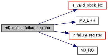
| M0_INTERNAL int | m0_sns_ir_failure_register (struct m0_bufvec *recov_addr, uint32_t failed_index, struct m0_sns_ir *ir) |
| M0_INTERNAL int | m0_sns_ir_init (const struct m0_parity_math *math, uint32_t local_nr, struct m0_sns_ir *ir) |
| M0_INTERNAL int | m0_sns_ir_mat_compute (struct m0_sns_ir *ir) |
| M0_INTERNAL int | m0_sns_ir_recover (struct m0_sns_ir *ir, struct m0_bufvec *bufvec, const struct m0_bitmap *bitmap, uint32_t failed_index, enum m0_sns_ir_block_type block_type) |
| M0_INTERNAL void | m0_sns_ir_fini (struct m0_sns_ir *ir) |
Detailed Description
Highlights
- Algorithm is distributed.
- Algorithm is not symmetric for data and parity blocks.
- Vandermonde matrix is used as an encoding matrix for Reed-Solomon encoding.
Discussion
After encountering a failure, SNS client initializes the incremental recovery module by calling m0_sns_ir_init(). Followed by that it reports failed blocks with m0_sns_ir_failure_register(). Once all failed blocks are registered, a call to m0_sns_ir_mat_compute() is placed. During this initialization the recovery module constructs a recovery matrix associated with failed blocks.
Once initialization is over, client passes available blocks to recovery module using the function m0_sns_ir_recover(). This function uses the fact that a lost block can be represented as a linear combination of alive blocks. It keeps accumulating data from input alive blocks, as SNS client passes it. Various parameters to m0_sns_ir_recover() tell the recovery routine how to use an incoming alive block for recovery. We will see how m0_sns_ir_recover() works using a simple example. Suppose we have four blocks in a parity group, b0 to b3, of which two have failed (say b0 and b1). Assume that these blocks satisfy following equations:
Note that each u_{i} is a constant coefficient, which gets computed during m0_sns_ir_compute_mat(). When block b2 becomes available to SNS client, it submits it using m0_sns_ir_recover(). This routine then updates in-memory copies of b0 and b1 as below:
Next, when block b3 gets submitted, m0_sns_ir_recover() adds its contribution cumulatively.
We call this mode of recovery as incremental recovery, where failed blocks get recovered incrementally for each input alive block. In all, there are three use-cases as below
- All failed blocks are data blocks.
- All failed blocks are parity blocks.
- Failed blocks are mixture of data and parity blocks.
It is worth noting that recovery of a lost parity block requires all data blocks. Hence in the third case above, we first require to recover all lost data blocks and then use recovered data blocks for restoring lost parity blocks. SNS client being unaware of dependencies between lost and available blocks, submits all available blocks to recovery module. When contribution by all available blocks is received at a destination node for a lost block, then SNS client marks recovery of that lost block as complete.
This algorithm works in three phases listed below:
- Phase1: transform alive blocks present locally on each node.
- Phase2: transform partially recovered data-blocks (from phase1 above) for failed parity-blocks.
- Phase3: add partially recovered blocks from last two phases at nodes where respective spare resides. In the first phase each node updates in-memory buffers for lost-blocks using in-memory buffers for alive blocks, local to the node. If the set of lost blocks consists of both data as well as parity blocks, then in the second phase, contribution of the partially recovered data blocks towards lost parity blocks gets computed. SNS client achieves this by calling m0_sns_ir_local_xform(). At this stage, if we add in-memory buffers of a lost block residing over all the nodes, then we would get a recovered block. In order to achieve this, each node sends an in-memory buffer of a lost block, to a node at which the spare for that block resides. Node at the receiving end then passes incoming blocks to m0_sns_ir_recover(). This completes the third phase. Nodes that do not have any spare block, do not have any computations in the last phase. Next section illustrates entire recovery process using an example.
Use-case
Consider a case of six data blocks, two parity blocks, and two spare blocks, distributed over four nodes. Assume following mapping between data/parity/spare blocks and nodes. di represents the i^th data block, pi represents the i^th parity block, si represents i^th spare block, and Ni represents the i^th node.
                 ________________________
                *                        *
                *  d0, p0, s0     --> N0 *
                *  d2, p1         --> N1 *
                *  d1, d3, d5     --> N2 *
                *  d4, s1         --> N3 *
                *________________________*
Assume that blocks d2 and p1 are lost. Let us assume that d2 gets restored at s0 and that of p1 gets restored at s1. Assume that d2 and p1 obey following equations:
In the equations above, vi and wi are constants, for each i. Note that we have clubbed those terms which can be evaluated at a same node. As discussed earlier, recovery of failed blocks is carried out in three phases. Following table illustrates all three phases in the context of our example. In the following table, we represent an in-memory buffer of a lost block di, on node Nj as di_Nj.
       Configuration:
        N = 6, K = 2
        Lost blocks: d2 and p1
         _____________________________________________________________________
        |Phase 1                      |Phase 2          |Phase 3                |
  ______|_____________________________|_________________|______________________|
  |  N0 |d2_N0 = w0.d0 + w5.p0        |p1_N0 += v2.d2_N0|send p1_N0 to N3      |
  |     |p1_N0 = v0.d0                |                 |d2_N0 += d2_N2 + d2_N3|
  |     |                             |                 |s0 = d2_N0            |
  |_____|_____________________________|_________________|______________________|
  |  N1 |                              |                 |                      |
  |     |                              |                 |                      |
  |_____|_____________________________|_________________|______________________|
  |  N2 |d2_N2 = w1.d1 + w2.d3 + w4.d5|p1_N2 += v2.d2_N2|send d2_N2 to N0      |
  |     |p1_N2 = v1.d1 + v3.d3 + v5.d5|                 |send p1_N2 to N3      |
  |_____|_____________________________|_________________|______________________|
  |  N3 |d2_N3 = w3.d4                |p1_N3 += v2.d2_N3|send d2_N3 to N0      |
  |     |p1_N3 = v4.d4                |                 |p1_N3 += p1_N0 + p1_N2|
  |     |                             |                 |s1 = p1_N3            |
  |_____|_____________________________|_________________|______________________|
*
We will now see how incremental-recovery APIs enable execution of various phases described above. Following code will show sequence of APIs that are executed at the node N0.
Once initialization is over, nodes start the compute phases described earlier. Following code illustrates this for the node N0.
Once SNS client runs out of local blocks at N0, Phase 1 gets over. Second phase gets executed using m0_sns_ir_local_xform(), as shown below:
Note that whenever a set of failed blocks does not contain both data and parity blocks, the only operation m0_sns_ir_local_xform() performs is changing the phase associated with recovery routine from M0_SI_BARE to M0_SI_XFORM. In the last phase, a node sends an in-memory buffer for a lost block to a node where respective spare unit resides. Receiving node passes incoming buffers to recovery routine.
With every buffer that SNS client submits to m0_sns_ir_recover(), a bitmap is submitted. Based upon indices of bits set in the bitmap, recovery module figures out the members from a parity group that have contributed to the incoming buffer. Hence, when a local block d0 gets submitted at node N0, a bitmap accompanying has only that bit set which represents d0. On the other hand, during third phase, a bitmap that accompanies d2_Ni has those bits set which represent blocks local to node Ni. When recovery gets over, node places a call to m0_sns_ir_fini().
Function Documentation
◆ m0_sns_ir_failure_register()
| M0_INTERNAL int m0_sns_ir_failure_register | ( | struct m0_bufvec * | recov_addr, |
| uint32_t | failed_index, | ||
| struct m0_sns_ir * | ir | ||
| ) |
Marks a failed block and populates the m0_parity_math_block structure associated with the failed block accordingly.
- Precondition
- block_idx < total_blocks
- total failures are less than maximum supported failures.
- Parameters
-
[in] recov_addr address at which failed block is to be restored. [in] failed_index index of the failed block in a parity group. ir holds recovery_matrix and other data for recovery.
- Return values
-
0 on success. -EDQUOT recovery is not possible, as number failed units exceed number of parity units.
Definition at line 453 of file parity_math.c.
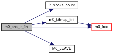
◆ m0_sns_ir_fini()
| M0_INTERNAL void m0_sns_ir_fini | ( | struct m0_sns_ir * | ir | ) |
When failures include both data and parity blocks, this function uses local copy of recovered (partially or fully) data-block for recovering failed parity block. On any node, this function can be triggered only once per parity group. Subsequent triggers will result into a no-operation.
- Parameters
-
ir holds information relevant for recovery
Definition at line 488 of file parity_math.c.
◆ m0_sns_ir_init()
| M0_INTERNAL int m0_sns_ir_init | ( | const struct m0_parity_math * | math, |
| uint32_t | local_nr, | ||
| struct m0_sns_ir * | ir | ||
| ) |
Populates the structure m0_sns_ir with fields relevant for recovery.
- Parameters
-
[in] math [in] local_nr Number of blocks from a parity group, that are available locally on a node. [out] ir
- Return values
-
0 on success -ENOMEM when it fails to allocate array of m0_sns_ir_block or when initialization of bitmap fails.
Definition at line 425 of file parity_math.c.
◆ m0_sns_ir_mat_compute()
| M0_INTERNAL int m0_sns_ir_mat_compute | ( | struct m0_sns_ir * | ir | ) |
Computes data-recovery matrix. Populates dependency bitmaps for failed blocks.
- Return values
-
0 on success. -ENOMEM on failure to acquire memory. -EDOM when input matrix is singular.
Definition at line 482 of file parity_math.c.
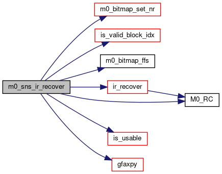
◆ m0_sns_ir_recover()
| M0_INTERNAL int m0_sns_ir_recover | ( | struct m0_sns_ir * | ir, |
| struct m0_bufvec * | bufvec, | ||
| const struct m0_bitmap * | bitmap, | ||
| uint32_t | failed_index, | ||
| enum m0_sns_ir_block_type | block_type | ||
| ) |
Computes the lost data incrementally using an incoming block.
- Precondition
- ergo(m0_bitmap_set_nr > 1, failed_index < total_blocks)
- Parameters
-
ir holds recovery matrix, and destination address for a failed block(s) to be recovered. [in] bufvec input bufvec to be used for recovery. This can be one of the available data/parity blocks or a linear combination of a subset of them. [in] bitmap indicates which of the available data/parity blocks have contributed towards the input bufvec. [in] failed_index index of a failed block for which the input bufvec is to be used. [in] block_type indicates whether incoming block is placed locally on a node or coming from a remote node. All remote blocks are assumed to be transformed.
Definition at line 503 of file parity_math.c.